In my previous post, I was finishing off the camera mounts and other components to attach the Red Edge to the frame. The 3D printed parts were warping and causing problems with the leg extenders. Over the past few days I finished the project in pretty good time.
To start off, I had to figure out how to build the leg extenders. The 3D printer was a good first start to get some tests for sizing but ultimately I decided not to use it. The parts were always a little bit too tight and threatened to crack in the threaded portion of the leg mounts.
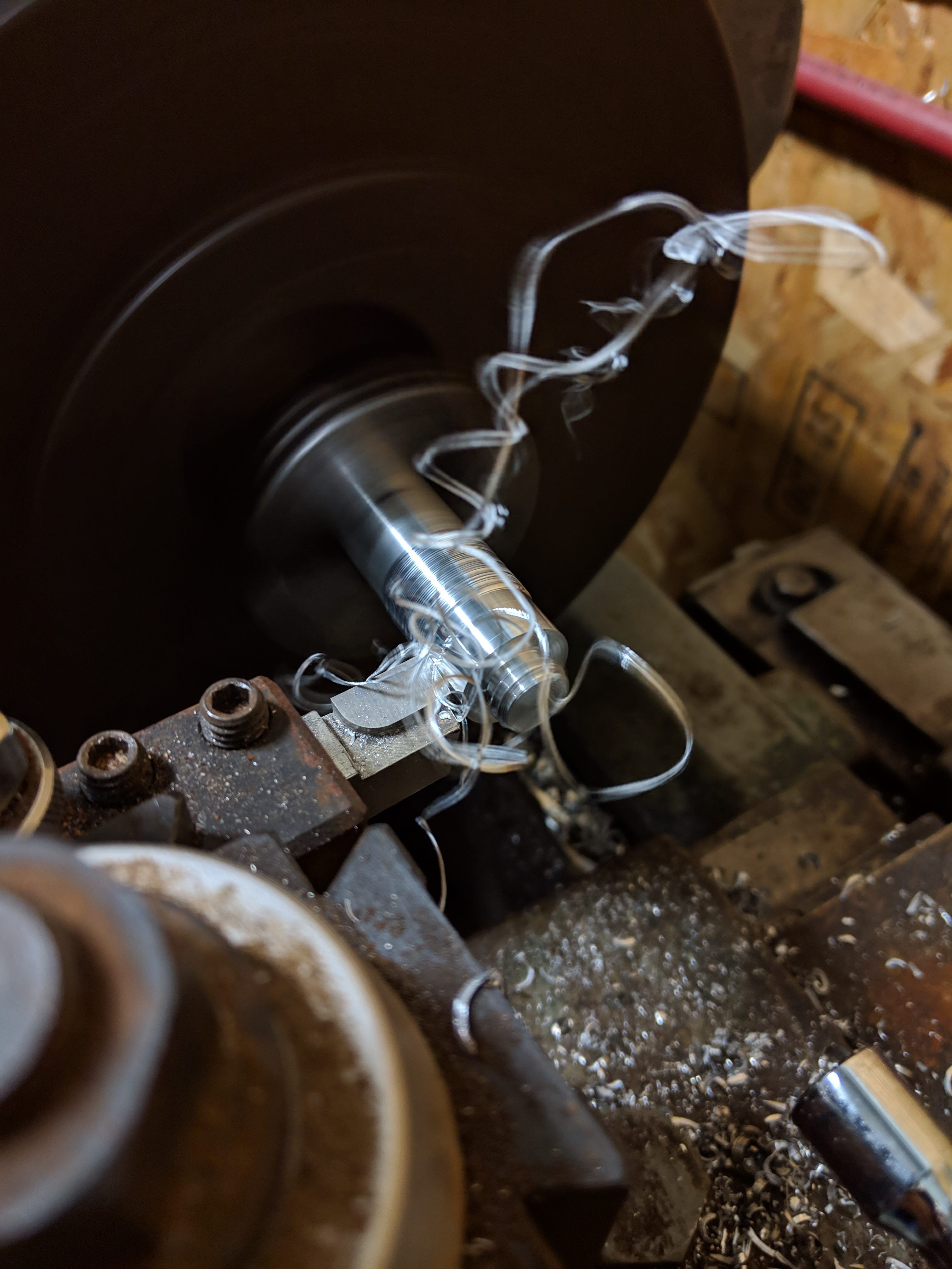
With 3D printing no longer being an option, I decided to machine the parts out of aluminum. I bought some 6061 alloy aluminum from McMaster Carr and, with the help of my dad, machined the parts on his lathe. We first machined the outside diameter to tolerance then drilled and tapped the hole for the female side which would interface with the leg. To reduce weight of the parts, we made the hole deeper than necessary which makes them partially hollow.

Inside diameter bored with outer diameter partially machined away
Reducing outer diameter on the lathe
The hard part to machine was the male end of the leg extender. While many lathes have an automatic thread cutting mechanism, the gearing on our lathe can only cut imperial threads while the Matrice uses metric threads. To get around this, we had to use a die set to thread the male end of the extender. I couldn’t get any pictures of this part since it required a lot of attention to detail and both hands.

Threads cut on outer diameter
One completed leg extender and leg
Now that both ends were machined, we just had to repeat the whole process 3 more times to finish off the project. Everything went smoothly from there on and the pieces fit on the Matrice perfectly. In all I believe we spent 3 hours machining the leg extenders.

Leg extender installed in Matrice
The final step to finish the project was to wire the camera up and install the GPS onto the mast. Since most of the electronics between the BEC, camera, and GPS mast were already wired from their previous installment, my work here was quite easy. I cut the GPS cable in half and added an extra 8″ of 6 conductor cable between them to extend it and covered it all with heat shrink.
To power the camera, I decided to draw power from the flight batteries using the XT-30 connectors on the underside of the frame. About 20 minutes later I had an adapter built to convert the XT-30 connector to the JST connector used in the BEC.
Wanting to keep things simple The mast on the airframe is about 1mm larger in diameter than the hole in the underside of the GPS platform. To get around this, I found a metal rod that was the same diameter as the hole in the GPS platform and used zip ties to attach it to the larger carbon rod on the airframe. Future flight tests will show if this was an effective mounting method or if the zip ties allow the mast to rotate too easily.

GPS masts
Over all this project was quite simple and straight forward. While the 3D printer issues caused many headaches along the way, I was able to work around them using the lathe. I still have yet to weigh the system after all of the additional hardware was added but I think it will fly without too many issues. If I do have to reduce weight further, I can modify the camera mounting block to be lighter but I would prefer to avoid this since I would have to work on the printer more to get it just right.