In my previous post, I discussed the ongoing project of getting a small desktop CNC running and some of the challenges I have faced along the way. In this post, I will be discussing some of the progress I have made in constructing an enclosure for the CNC and its electronics.
Before I start discussing how I built the enclosure, I should discuss my design requirements which guided my decisions when creating the enclosure. I had a number of requirements I wanted to follow including being easily constructed using scrap wood laying around the house, being fully enclosed to capture dust created by the machine, and having enough space to allow me to redesign different components of the machine without rebuilding the enclosure to accommodate larger parts. I also wanted the enclosure to have provisions to allow clamps to be placed wherever they may be required since stock material can be challenging to hold. A side goal was to be able to open both the front and back of the enclosure so I can machine small sections of a longer piece of stock material. After considering all of these goals, I took inventory of the different pieces of lumber I had available and began designing the enclosure in CATIA.
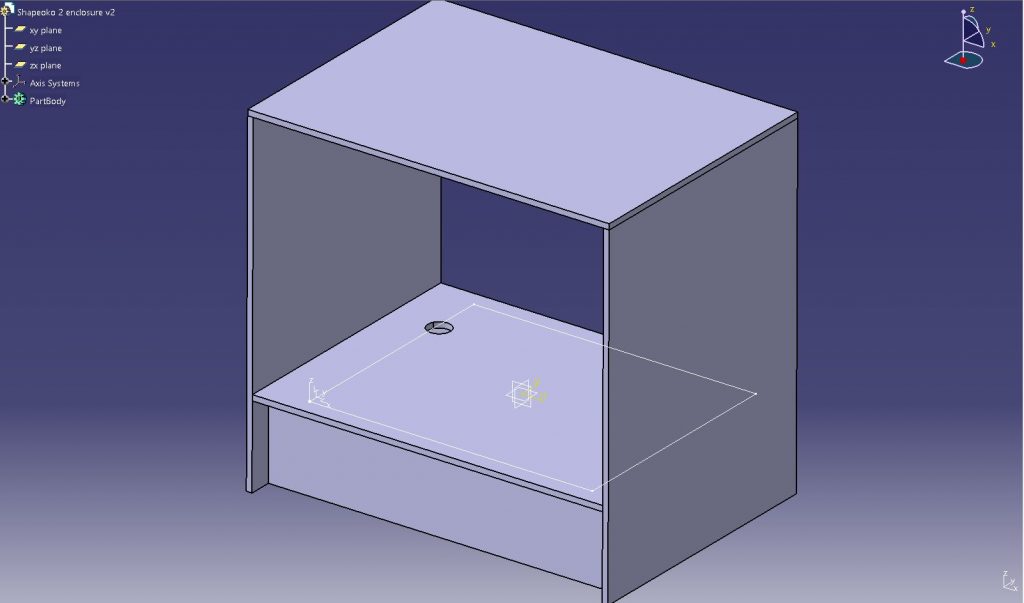
The above image shows my final design for the enclosure. I managed to use all of the scrap wood around my house to create this design and have enough space to mount the CNC inside and route cables through the hole in the back of the base. The front and back sides of the enclosure are also inset by 2 inches, allowing enough space to place clamps on the edge for stock material holding. I decided to wait to design the front and back doors of the enclosure since the cuts on the wood might not be perfect during construction. When the enclosure is fully built, I will be able to update the CATIA drawings with the as-built dimensions so I can create a digital twin of what exists in the physical world.
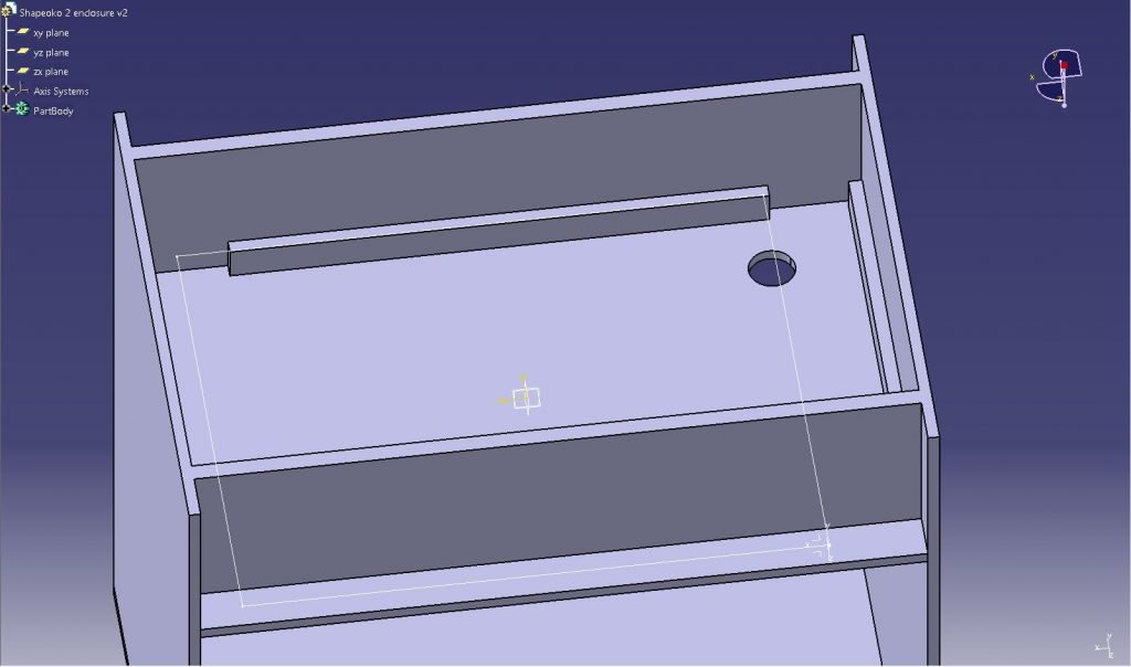
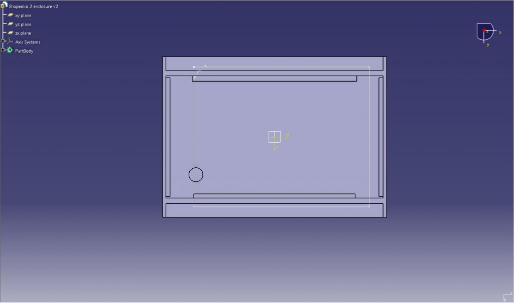
In the above image, my planned design for the bottom of the enclosure can be seen. The side walls are supported by a series of four small strips which will hold the screws so I can avoid warping the plywood. This compartment is quite large being almost 7.5″ deep and covering a 31″ by 17.5″ area. I plan to use this area for electronics and possibly a small vacuum to clean the CNC if I can find one that fits. The extra area will also help with cable management since I will now have no excuses for poor wiring practices.
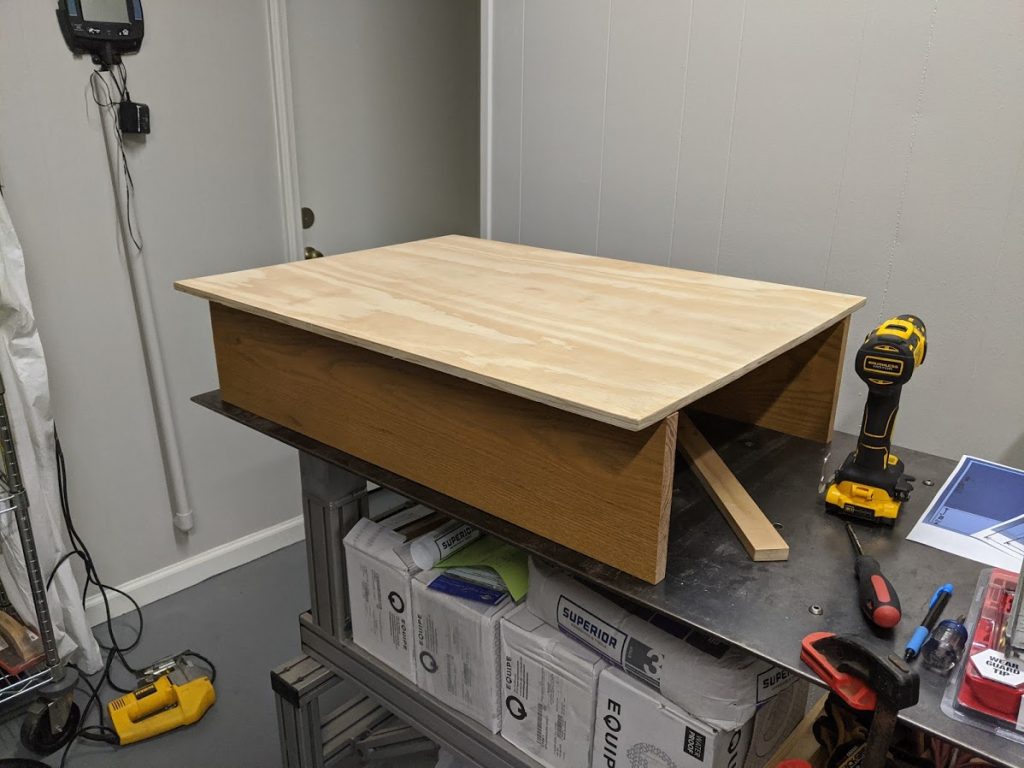
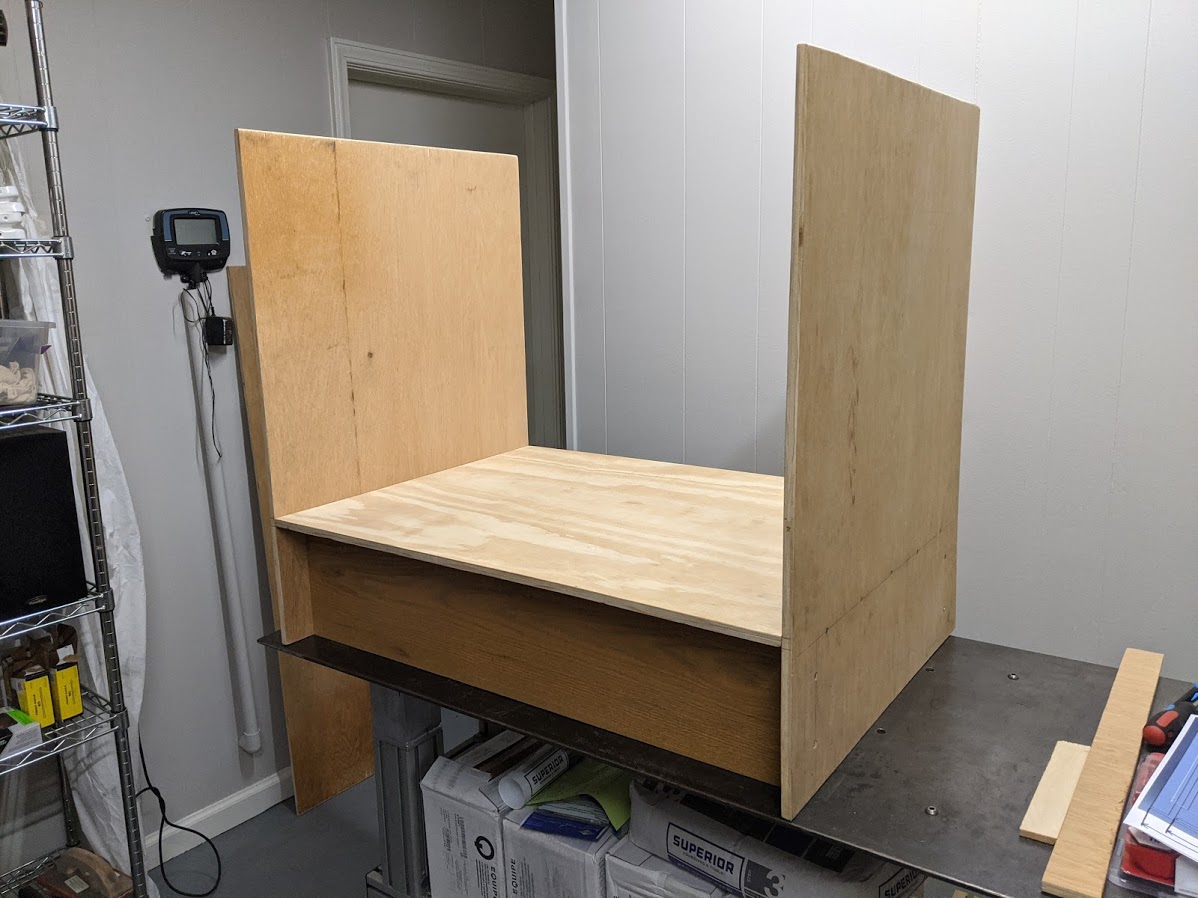
With the enclosure fully designed in CATIA, it was time to begin building. I planned out all of my cuts beforehand, made notes on my phone so I knew the dimensions of each part, then got to work. The first step was cutting the baseplate which the CNC will sit on and installing the front and back boards. I used a jig saw for most of this since the table saw was elsewhere for another project, but I think the results came out really well. At this stage the stand was already very stable and could probably hold my weight if I were to sit on it.
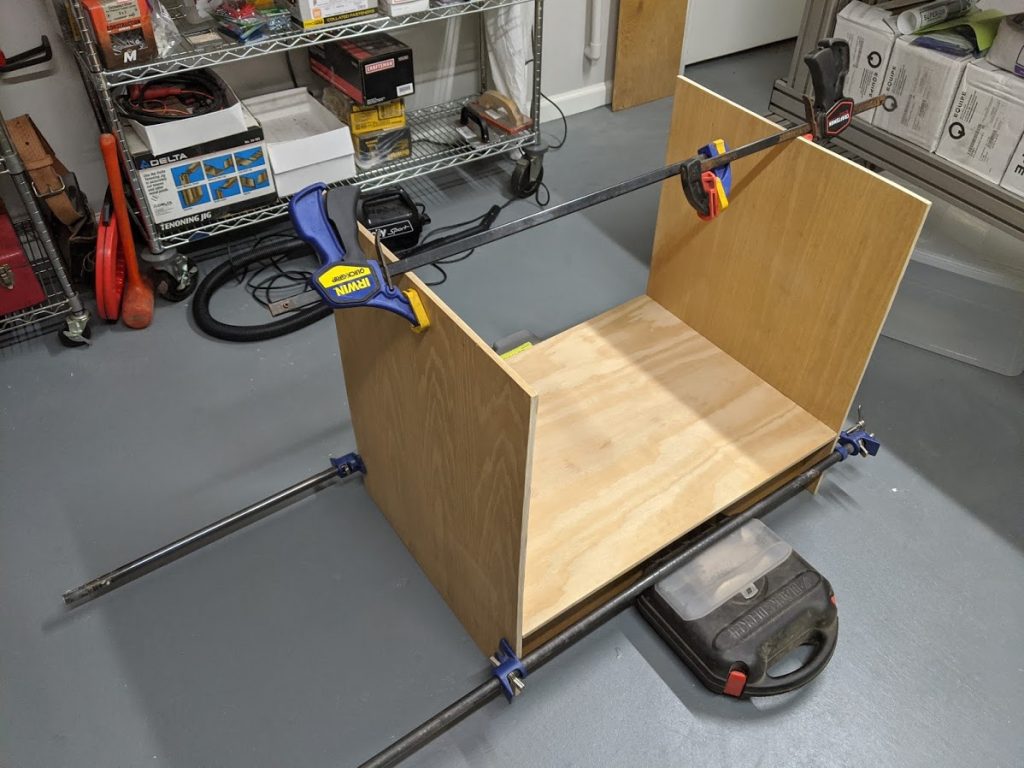
Next up was to build the sides of the enclosure. This step involved more use of the jigsaw and fit testing as can be seen in the above image. The left side was nearly perfect, but the right side needed to be shimmed slightly to make it fit straight. Once that was done, I was able to drill the holes for the screws and install the sides.
I ultimately ended up deciding to wait to build the top surface and front and back doors to the enclosure until later since the electronics install will go smoother without them in the way. With the enclosure built, I am ready to begin installing electronics and mounting the CNC. I have plenty of screw terminal blocks which should make the process easier, but that will be saved for the next post.