In my last post, I described the designing and building of an enclosure for my CNC. I have been doing a lot of work to it over the past couple days and figured now would be a good time to make an update on the progress.
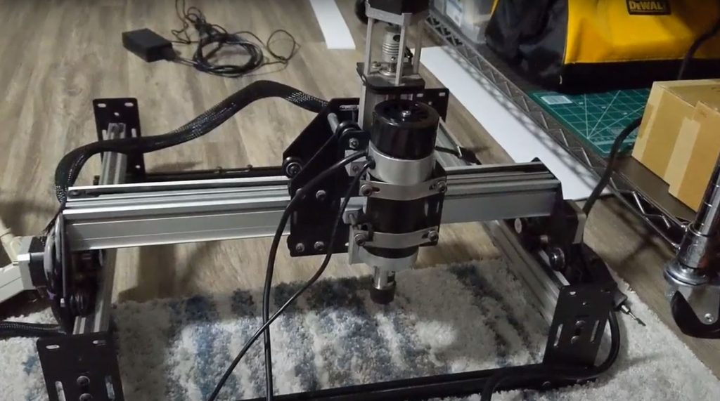
To start the renovations off, I decided to remove all the wiring from the temporary electronics enclosure I had previously made. I also removed all zip ties from the wiring bundles so I could access everything. My reasoning for doing this was that I had bought a new brushless spindle from ebay to replace the Dremel the CNC was previously using. This upgrade will allow me to use larger tools and hopefully reduce the runout a bit.
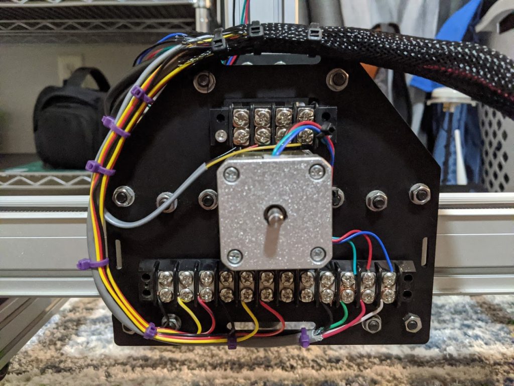
With the new spindle installed, I decided to install screw terminal blocks on the back of the X axis plate. This will allow me to quickly replace components without running new cables every time I make a change. I also ran 10 additional wires to the X axis for future expansion with limit switches, automatic tool probing, and other similar upgrades. I also added more terminal blocks to the left Y axis mount plate in a similar fashion.
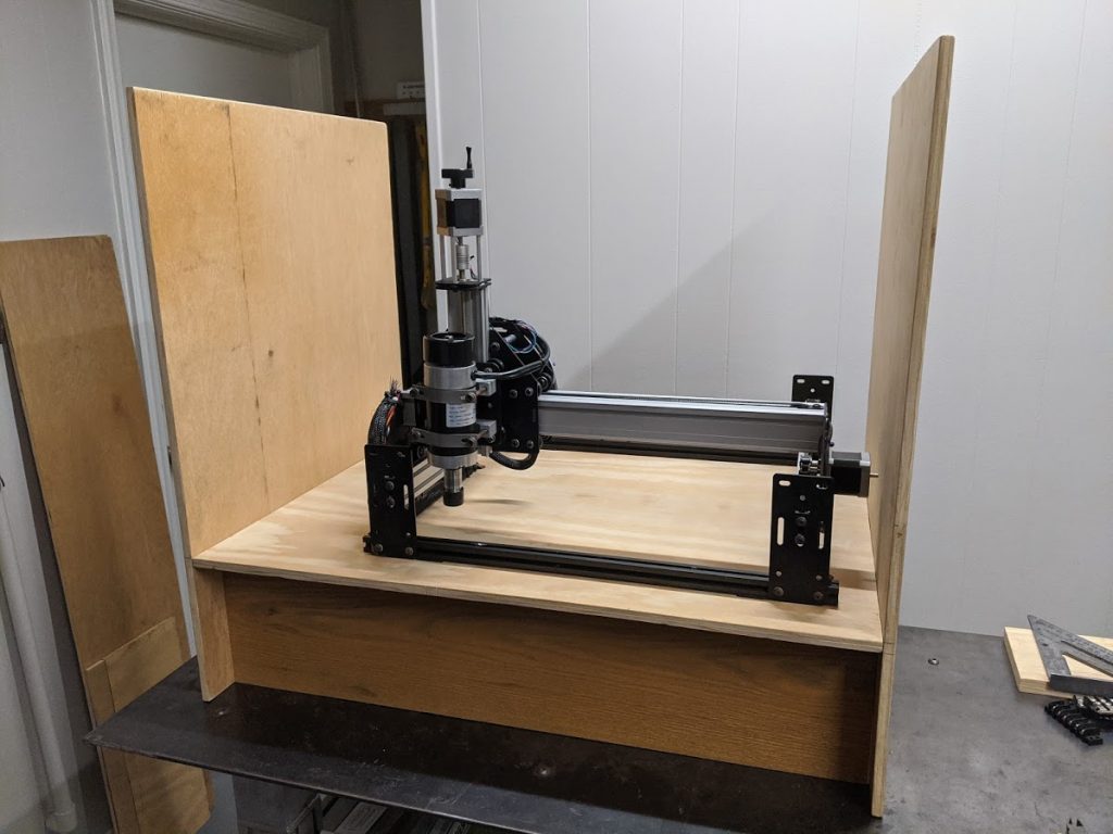
The next step in this project was to mount the CNC onto the baseplate of the enclosure. I did this by drilling a series of holes in the 2020 aluminum extrusions of the CNC so I can screw it into the baseplate. I also found some weather stripping to go between the baseplate and the extrusions to reduce vibrations. This mounting method is a little crude, but it does allow me to adjust the alignment of the extrusions if I should find that one of them is slightly slanted.
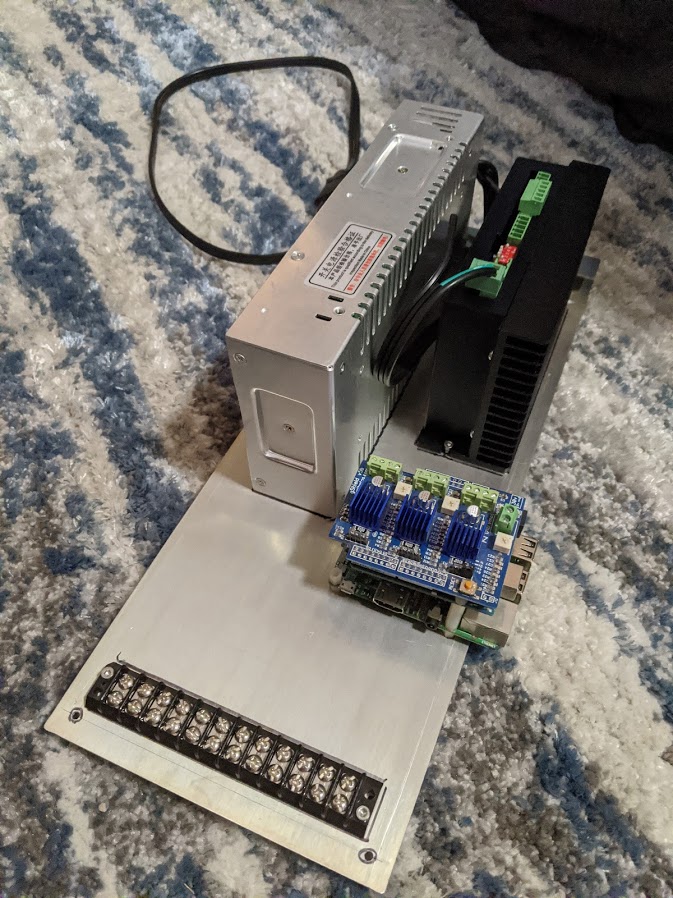
With the machine fully mounted on the top of the enclosure, it was time to begin mounting electronics to the underside. The new spindle needs a 48 volt power supply and a specialized Variable Frequency Drive, or VFD for short, to power it. This system first converts the 110v AC from the electrical outlet into 48v DC in the power supply. The power supply then sends the regulated power out to the VFD which converts the 48V DC into a series of electrical pulses which then drive the brushless motor. This motor also has a hall effect sensor built in which means the VFD can identify when the spindle is slowing down due to increased loads and compensate by increasing the power.
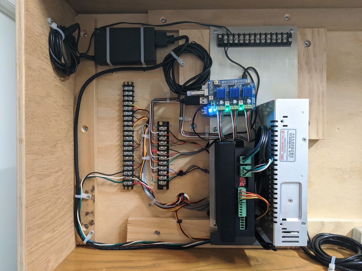
The 48v power supply and VFD can be seen as the large steel and black components mounted to the sheet metal. The Arduino based CNC controller and Raspberry Pi are also mounted to the sheet using a series of standoffs. This helps keep all the logic components in one place so I don’t have to route long wires.
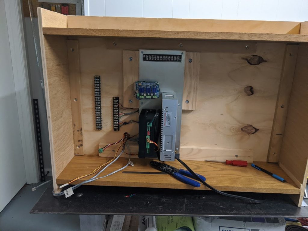
Once everything was screwed down to the sheet metal, it was time to mount it into the underside of the enclosure. This step was relatively easy since I could screw the whole thing into a handful of pieces of wood. I can remove the sheet metal for access to the backside by taking out only 6 screws along the edges of the sheet. I also installed a few more screw terminal blocks to tidy up the wiring. The right screw terminal block is exclusively used for stepper motors while the left side screw terminal block is used for the spindle motor connections and limit switches.
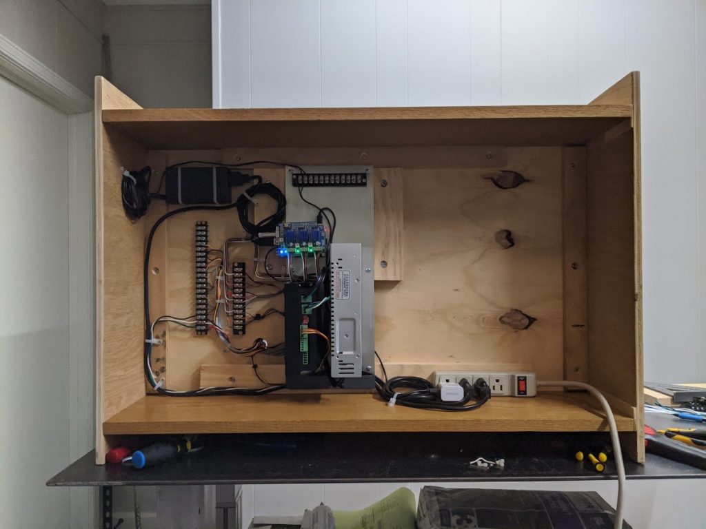
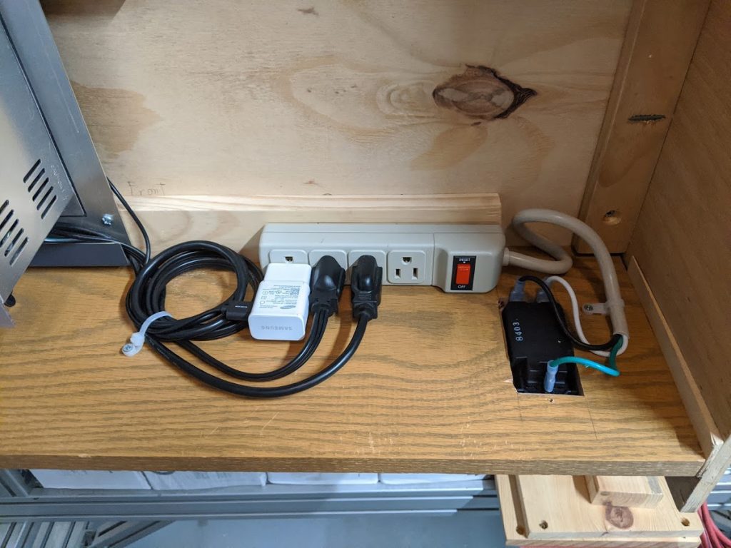
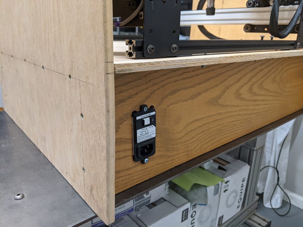
After a bit more wiring and cable management, I had a functioning system. In the top left corner I installed a 12v power supply to run the stepper motors. The bottom right corner has a power strip which makes the wiring a bit safer by adding a circuit breaker which can trip if something goes wrong. I didn’t like having a cable draping out of the back of the CNC, so I decided to add an IEC connector to the rear panel of the enclosure. This particular connector includes a 10A circuit breaker of its own which acts as a backup in case the power strip doesn’t break the circuit in an overload situation.
With everything wired up, the machine is ready for some test cuts. I will likely be doing this with the front board of the CNC as it is currently too thick to install a series of buttons for basic start/stop functions and a basic pocketing operation can easily clear out the material for this purpose. That will likely be a future post. I am also concerned that the 12v power supply might not be enough to drive the stepper motors efficiently, but I will have to address that later.